
Fabrication Instructions for the Vertex Dynamic
with Vertex R.O.M. & Double Action Ankle Joint
The Key to the function of the Vertex Dynamic Ankle Joint with the Vertex R.O.M. comes from the proper placement and alignment of the joints on the positive mold. Here are some suggestions that can help to achieve this goal.
- Prior to applying the casting material care should be taken to mark with an indelible pencil the distal tip of the medial and lateral malleolus, and desired placement of the ankle joint centers.
- If you wish to use the threaded positioning rod, this should be applied through the Dynamic Ankle Joint Distal (Bottom Screw Hole) Axis and the Vertex Center Axis prior to filling the negative cast. Proper placement of the rod will help ensure correct alignment of the ankle joints.
- The mold is filled with molding plaster.
- Modify mold as desired, the threaded rod may be removed during this process.
- Apply fabrication spacer pads.
- Disassemble ankle joints.
- Thread the midsections bushings on both the medial and lateral sides of the threaded rod, tighten the bushings against the spacer pads/positive mold.
- Contour proximal and distal bars to mold as desired.
- Attach and tighten down ankle joints with two additional hex nuts.
- Remove excess threaded rod.
- Prior to vacuum forming, the space between the joints and positive mold should be filled with clay to prevent the plastic from forming completely around the ankle joint.
- Vacuum form positive mold.
- Mark trim lines and remove from positive mold.
- Mark ankle joint centers and cut through the posterior aspect of the plastic through the ankle joints axis. Note: You may want to mark the ankle joints medial or lateral to avoid confusion during the final assembly.
- Finish plastic edges.
- Reassemble ankle joints.
- Mark and drill the proximal and distal attachment holes with appropriate drill bit.
- Attach joints into plastic using the attachment screws provided.
- Remember to always use loc-tite on all screws used in final assembly.
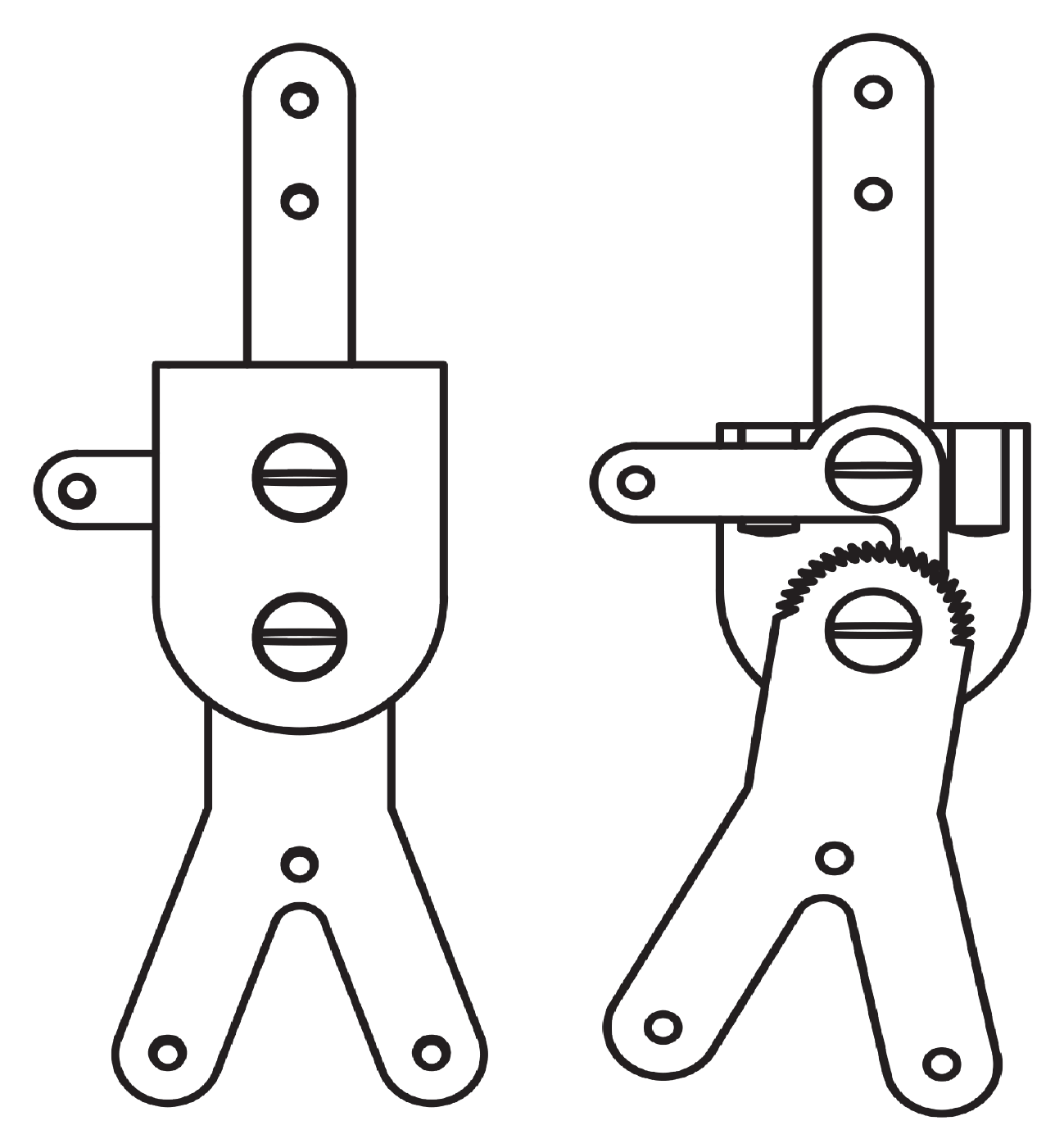


Vertex Dynamic Ratchet Lock
Ankle Joint

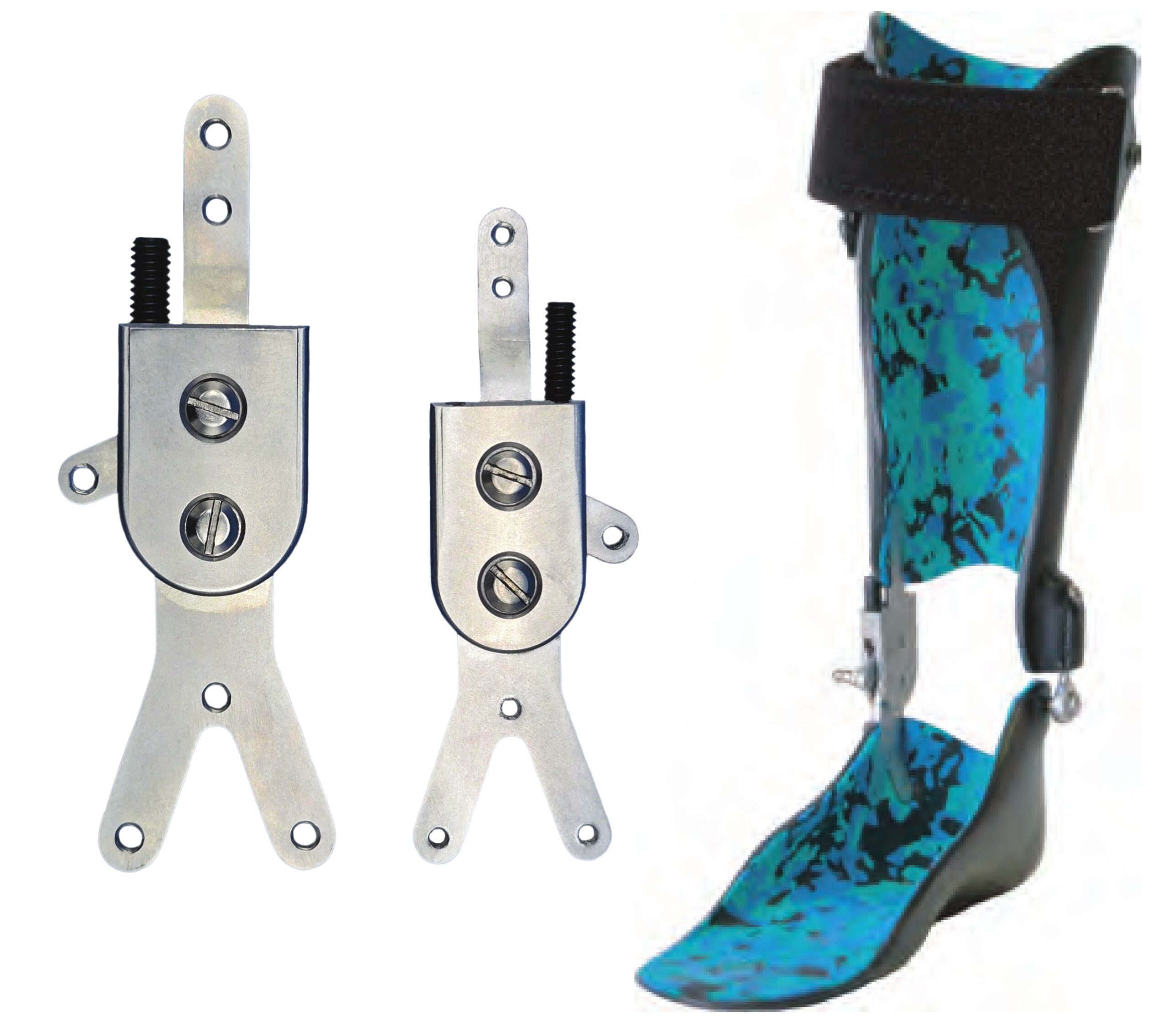

Fabrication Instructions for the Vertex Dynamic
with V-3 Self Aligning Ankle Joint
- Select appropriate ankle joint axis on positive mold.
- Pull vacuum forming hose onto the positive mold.
- Tack on the V3 molding dummy with the nails provided on top of the vacuum hose, and place the Dynamic Joint on contra-lateral side of cast positioning the distal axis hole in alignment with the V-3 axis. Please note this alignment does not have to be exact since the V-3 is a self aligning joint, however, it is recommended to be as accurate as possible.
- The articulating axis of the V-3 ankle joint is the center of the oval raised portion on the molding dummy.
- Contour Dynamic Ankle Joint as desired over Malleolus, apply Dynamic fabrication molding pad on positive mold, place joint on pad, and fill any space with clay to prevent plastic from forming completely around the ankle joint.
- Thermoform the plastic in your usual fashion for the type of thermoplastic selected.
- Select your trim lines and remove plastic from mold (please note suggested trim line for the ankle joint). Cut off AFO as if it were a solid ankle in order to preserve the molding dummy for continued use.
- Remove V-3 molding dummy and Dynamic Ankle Joint from the cavities in the AFO.
- Trim and Grind plastic in normal fashion.
- Using an #19 drill bit, drill the proximal attachment hole for the V-3 Joint.
- Using an 3/16” drill bit, drill the center articulating axis hole for the V-3 Joint.
- Heat the 10-32 brass fitting, and press fit into articulating axis of the V-3 Joint until the bottom is flush with the inside of the plastic.
- Slide proximal V-3 piece into the cavity, and secure with the attachment screw.
- Secure the V-3 self-aligning rod end with the 10-32 screw into the brass bushing.
- Remember to lock-tite all attachment screws.
- Drill holes for the Dynamic – 8/32” attachment screws using 5/32” drill bit, and attach to AFO.
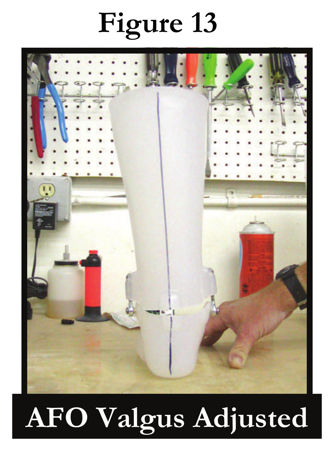
- To adjust the V3 for Varus or Valgus, simply remove one of the 10-32 center screws, adjust the self-aligning rod end to the appropriate height and replace the 10-32 center screw.
- It is our recommendation that at least 3/16” of the thread on the self-aligning rod end stay inside the proximal section.
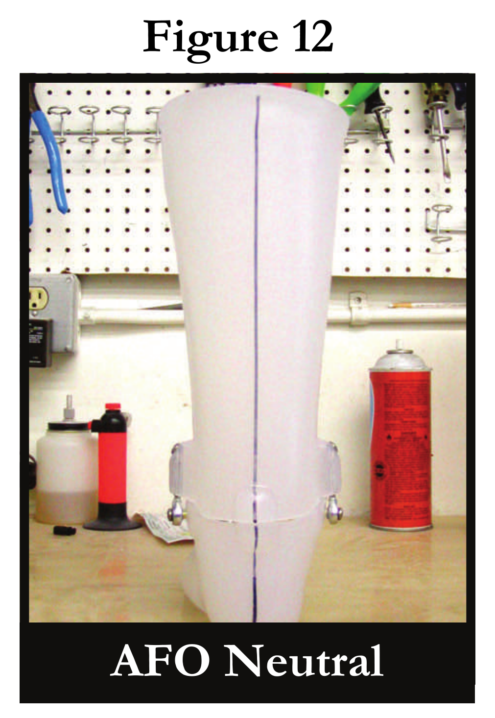
- Please see Figure 12 and Figure 13 for a visual example of how you can easily change the Varus or Valgus angle in the AFO.
Fabrication Instructions for the Vertex Dynamic
with Baseline Free Motion Ankle Joint
The Key to the function of the Dynamic Ankle Joint with the Baseline Free Ankle Joint comes from the proper placement and alignment of the joints on the positive mold. Here are some suggestions that can help to achieve this goal.
- Prior to applying the casting material care should be taken to mark with an indelible pencil the distal tip of the medial and lateral malleolus, and desired placement of the ankle joint centers.
- If you wish to use the threaded positioning rod, this should be applied through the Dynamic Ankle Joint’s Distal (Bottom Screw Hole) Axis and the Baseline Center Axis prior to filling the negative cast. Proper placement of the rod will help ensure correct alignment of the ankle joints.
- The mold is filled with molding plaster.
- Modify mold as desired, the threaded rod may be removed during this process.
- Apply fabrication spacer pads.
- Disassemble ankle joints.
- Thread the midsection bushings on both the medial and lateral sides of the threaded rod, tighten the bushings against the spacers pads/positive mold.
- Contour proximal and distal bars to mold as desired.
- Attach and tighten down ankle joints with two additional hex nuts.
- Remove excess threaded rod.
- Prior to vacuum forming, the space between the joints/spacer pads and positive mold should be filled with clay to prevent the plastic from forming completely around the ankle joint.
- Vacuum form positive mold.
- Mark trim lines and remove from positive mold.
- Mark ankle joint centers and cut through the posterior aspect of the plastic through the ankle joints axis. Note: You may want to mark the ankle joints medial or lateral to avoid confusion during the final assembly.
- Finish plastic edges.
- Reassemble ankle joints.
- Mark and drill the proximal and distal attachment holes with appropriate drill bit.
- Attach joints into the plastic using the attachment screws provided.
- Remember to always use loc-tite on all screws used in final assembly.
Utilizing the Vertex Dynamic Engagement Strap:
- Attach the Dynamic Ankle Engagement Strap on the same side of the Dynamic Ankle Joint.
- Be Sure Chafe to Strap is placed proximal/above ankle joint. Position engagement strap in alignment with the hammer on the Dynamic Ankle Joint.
- The tension created by tightening the strap creates the resistance needed to engage the Dynamic mechanism.
*Please note you may use another form of an engagement mechanism if desired, and may attach at a different location if desired. (i.e. elastic, strap and screw fastener, lever lock system.)